Some time ago I replaced my HPE 3PAR 7400 array in my homelab with a new HPE Nimble storage array HF20.
HPE 3PAR had an interesting feature called Direct Attach aka FlatSAN, that allows to connect your 3PAR array directly to the Virtual Connect modules inside a C7000 BladeSystem and Synergy bladed solution, without the need of FC switches for SAN connectivity. This configuration lowers the price of your solution, and removes the complexity of SAN management.
Now it was important for me to validate this feature as well with the brand new Nimble array that I was planning to buy. I found out that it was supported but nowhere I could find a proof of this.
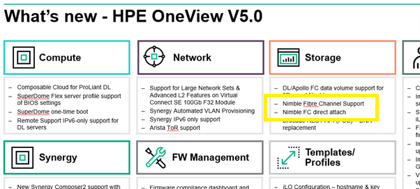
Luckily, inside the OneView 5.0 presentation I found a little statement about Fibre Channel Support with Direct Attach.
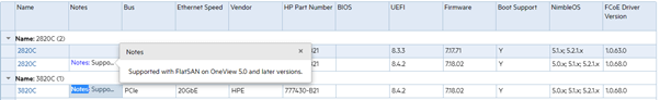
Also HPE SPOCK, being the reference database of all validated storage configurations within HPE, showed me via my 3820C CNA adapter in my Synergy SY480 blade through a well hidden side note that it was supported when using OneView 5.0 or higher in combination with Nimble OS 5.x or higher.
OK, let’s get started to find out!
Cabling
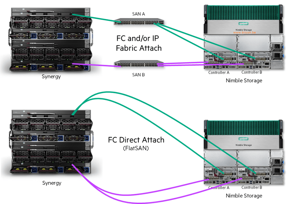
We start with the cabling. I found this picture how to cable a Nimble array with the Synergy frame. Quite obvious: redundant cabling meaning every Nimble controller needs an FC connection with each Virtual Connect Master Module in the Synergy frame.
When I need to do planned management on one of the controllers of the Nimble array, I still want redundant connectivity with both FC ports to my servers. Also when I need to do maintenance on my Virtual Connect Master modules I don’t want a fail-over of my Nimble controllers due to paths being down when a Virtual Connect Master Module reboots (or is unavailable). Makes sense. At the end of this article I show how you can validate this.
OneView configuration – LIG Logical Interconnect Group
The next important step is the configuration of the OneView software running on the Synergy Composer. Plenty of documentation on how to set it up with FC switches, however I could not find the details for the FlatSAN configuration. Luckily it was exactly the same as for my 3PAR configuration.
The most important thing to configure are the ports where the Nimble array will be connected with the Virtual Connect Master Modules. This is done within the LIG or Logical Interconnect Group.
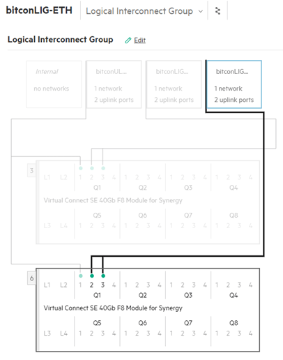
Besides the typical Ethernet Uplink Set(s) for network connectivity for your servers, you need to create now 2 FC Uplink Sets (like you would have 2 FC fabrics/zones in a switched fabric) with at least 2 ports per FC Uplink set. These 2 ports per uplink set will be used to connect at least 1 FC port per Nimble controller, which makes that every controller has a connection with every FC Uplink set.
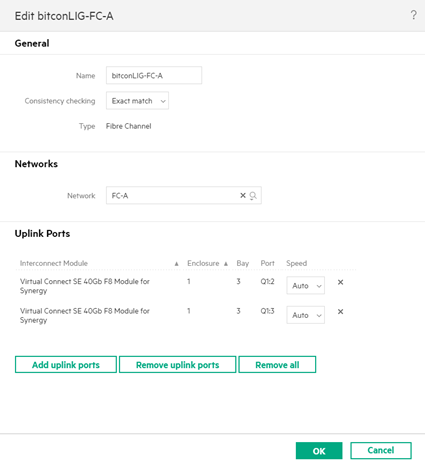
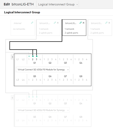
In this example I have created an FC Uplink Set A with 2 connections on the Virtual Connect Master Module in bay 3 on ports Q1:2 and Q1:3.
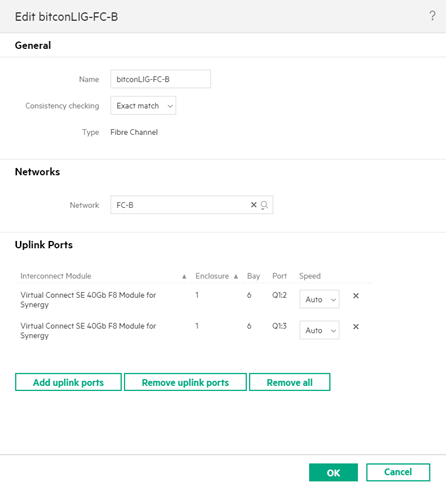
I did the same fore the second FC Uplink Set B with 2 connections to ports Q1:2 and Q1:3 on the Virtual Connect Master Module in bay 6.
OneView configuration – Networks
Once the LIG is created you can create the FC Networks that will be used in the Server Profiles (next and final step).
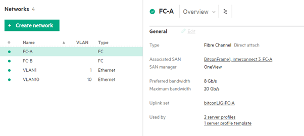
During the creation of the FC network you have the option through the drop-down box to select a Direct Attach network.
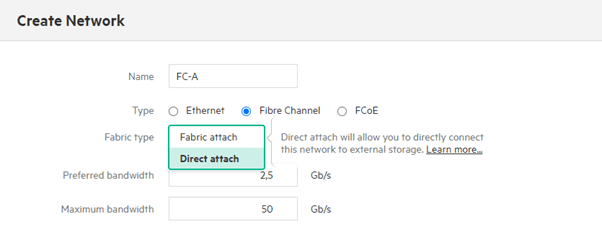
That’s it, do this for both FC networks A and B using their own appropriate LIG’s A & B.
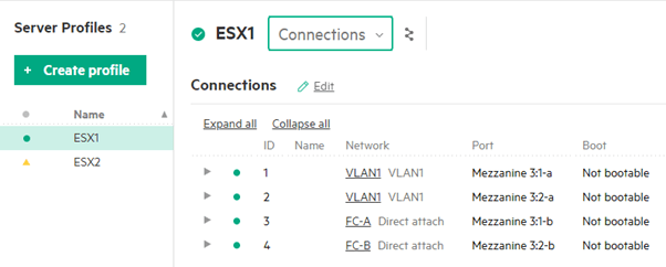
OneView configuration – Server Profiles
Finally it’s these 2 networks FC-A and FC-B that will be used within the OneView Server Profile, that will create the software-defined Ethernet and FC networks.
Final test
It is very easy to test the correct hardware setup and software configuration by rebooting 1 of the 2 controllers of the Nimble array, ideally the Standby controller since it will do no harm at all on your production environment. Or just unplug the 2 FC cables on your Nimble standby controller.
At that moment, the 2 FC connections of that controller will go down, giving you 2 red dots on the Logical Interconnect modules.
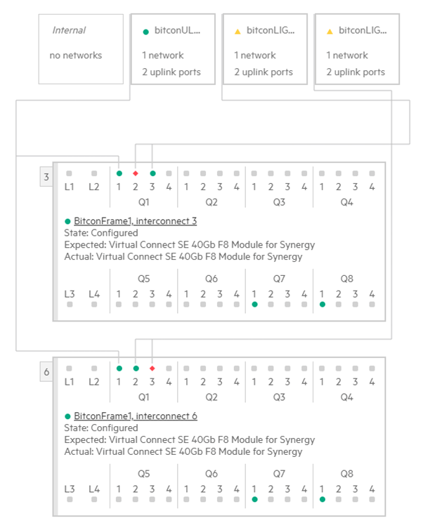
Ideally it should be like in the picture above, 1 connection is down per Virtual Connect Master Module.
If you see 2 red dots on the same Virtual Connect Master Module this means that the cabling is wrong.
For any support, training or consultancy needs on HPE based solutions, feel free to contact us.
Be social and share!