In my previous post I explained the installation and initial configuration of the HP Oneview management appliance.
In this second section I will dive deeper in the Network Configuration of HP Oneview.
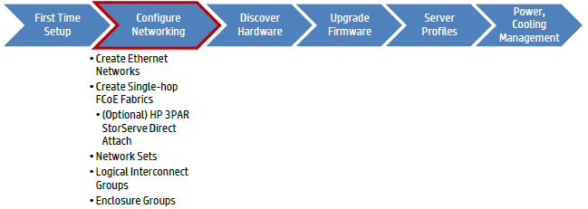
The steps I will cover in this post are creating Networks, Network Sets, Logical Interconnect Groups and Enclosure Groups.
Some new concepts
Yes Oneview uses some new objects compared to HP SIM and Virtual Connect Manager.
One feature of Oneview is the integration of all Virtual Connect Manager configurations running on your Virtual Connect (VC) modules in the blade enclosures, with or without VCEM Virtual Connect Enterprise Manager running on top of it.
Instead of creating multiple, stacked or non-stacked, VC domains, Shared Uplink Sets, Server Profiles and so on, this will be all centralized in 1 place being Oneview!
In HP Oneview you will recognize these new definitions:
Networks
Networks are objects within the appliance that define a particular Layer2 network or FCoE/FC Fabric. A Network will be an object you can assign to Server Profiles, Network Sets, and Logical Uplink Sets. The VLAN ID must be unique within the appliance, as HP OneView does not support Active/Active Virtual Connect networking configuration in this current version 1.0.
Similar to Virtual Connect provisioning all Ethernet Networks to all Ethernet modules within a Virtual Connect Domain, HP OneView provisions all defined Ethernet Networks to all managed Ethernet-capable modules.
Network Sets
Network Sets are aggregated networking objects that contain Networks. The Network Set will be an object you can assign to Network Connections within Server Profiles to greatly simplify multiple network configuration management tasks.
For instance, if you have a number of standard Networks required for Virtual Machine connectivity, which is different for physical servers, you can create different Network Sets for each host connectivity model.
Network Sets replace the Multiple Networks Virtual Connect concept, and becomes the only way to trunk multiple networks to a Network Connection.
Logical Interconnect Groups
Logical Interconnect Groups are similar to Virtual Connect Enterprise Manager Domain Groups, which define what modules are located within the enclosure and the module configurations like IGMP Snooping, Loop Protection, Multicast Filtering, etc. Uplink Sets define uplink connectivity for Ethernet, FCoE and FC Networks, and are members of a Logical Interconnect Groups.
The Logical Interconnect Group is then assigned to an Enclosure Group to complete the Enclosure configuration policy.
A Logical Interconnect is patterned after the Logical Interconnect Groups and is defined automatically once an Enclosure is added to the HP OneView console by associating it to an Enclosure Group.
Uplink Sets
Uplink Sets are synonymous with the Shared Uplink Set within Virtual Connect, in that it defines the uplink connectivity for selected networks.
An Uplink Set can either be an Ethernet or Fibre Channel type, but not both. With the HP OneView 1.0 release, Uplink Sets can only be configured in an Active/Standby design, and must connect to an 802.1q configured adjacent switch port(s).
Any defined Networks not associated with an Uplink Set become Internal Ethernet Networks to the Logical Interconnect, and are reported within the Logical Interconnect.
Active/Active configuration is planned in a future version.
Enclosure Groups
An Enclosure Group is a centralized configuration policy, similar to that of the Logical Interconnect Group, in which all associated Enclosures retrieve their configuration from.
With the HP OneView 1.0 version, the Enclosure Group will only define the Logical Interconnect Group association, and contain embedded, un-configurable management settings.
These management settings are SNMP, NTP and the HP SIM Single-Sign-On (SSO) Certificate for agentless management configuration.
HP Oneview Domain
An HP OneView Domain is a new concept to the Converged Infrastructure management framework. While you cannot create additional HP OneView Domains, the appliance itself is a single Domain construct.
An HP OneView Domain consists of one or more Logical Interconnect Groups, Uplink Sets, Networks and help to define how Server Profiles consume these resources. When definining a Network, it will be available within the HP OneView Domain for consumption by either a Logical Interconnect Groups, Logical Uplink Set, Logical Interconnect (for one-off configuration requirements) or Server Profiles (for Internal Only networks.)
Configuration
The first object to create is a Network.
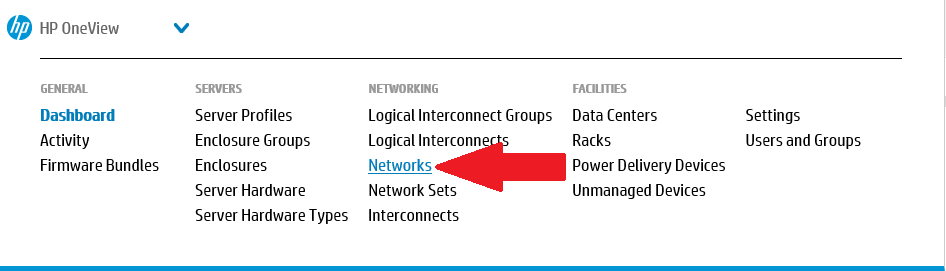
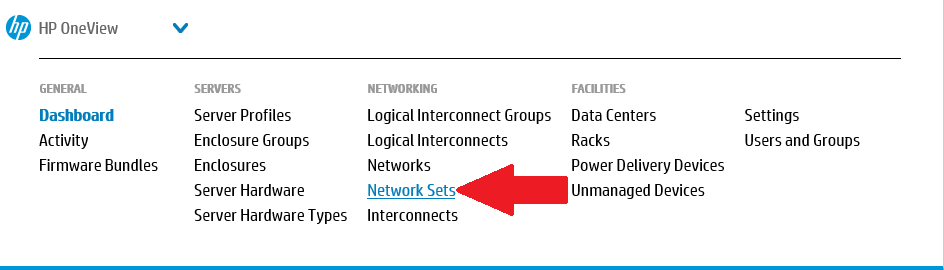
Select the Top Level Menu, under the Networking section select Networks
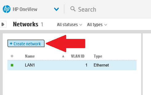
Click the +Create Network button at the top left.
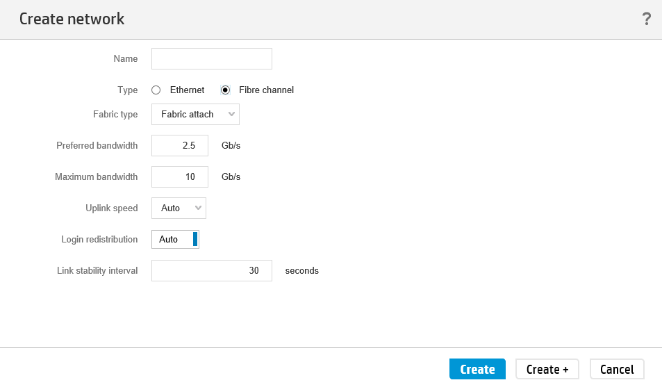
In the next window provide a name for the network and select the type of network. Choices are Ethernet or Fibre Channel.
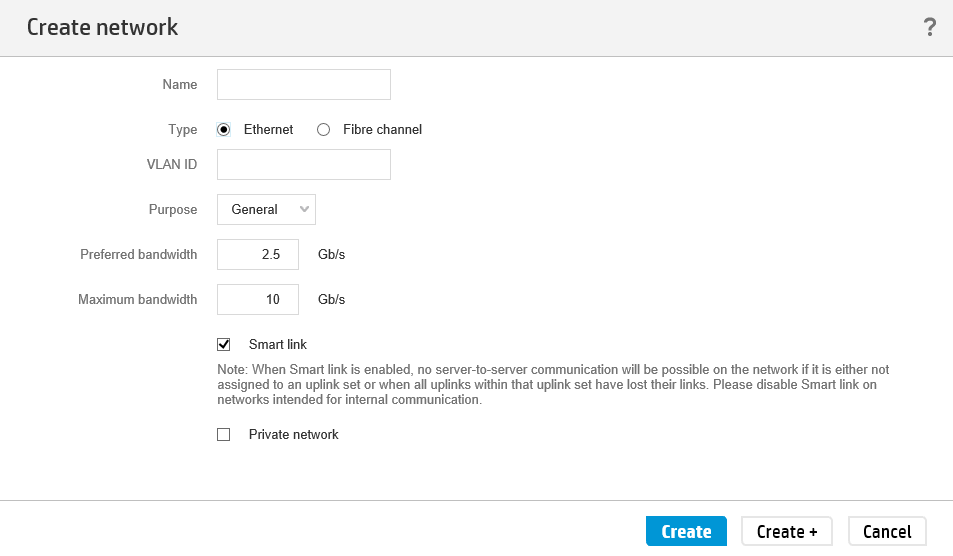
For Ethernet networks select the VLAN ID, set the purpose, preferred and maximum bandwidth, and if this network needs Smart Link and is a Private Network. These parameters were also available inside VC Manager.
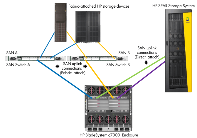
For Fibre Channel networks select the fabric type (Fabric Attach for connection to FC SAN switches or Direct Attach for Virtual Connect FlatSAN with HP 3PAR StoreServ Direct Attach.
Further Uplink speed, preferred and maximum bandwidth can be selected.
Once one or more networks are created in HP Oneview (per VLAN and per FC fabric) can these networks be logically bundled in a Network Set.
Select the Top Level Menu, under the Networking section select Networks
Click the +Create Network Set button at the top left.
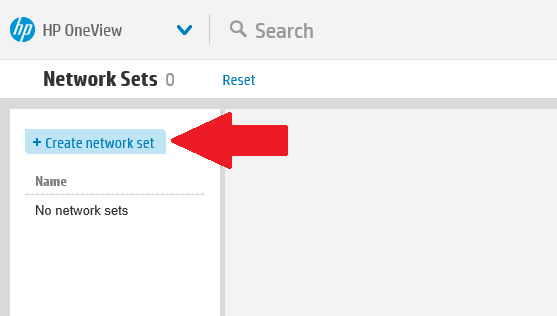
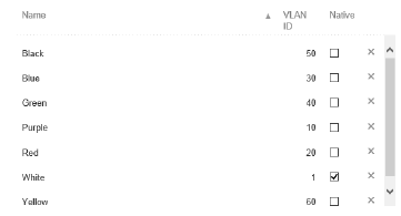
In the next window provide a name for the new Network Set and click the Add Networks button to select one or more networks
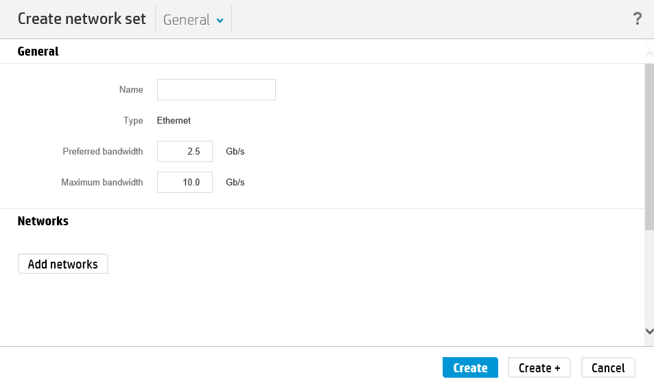
You can search for a network, or either click SHIFT/CTRL+Left Mouse Click to select all or selective networks to be added to the Network Set.
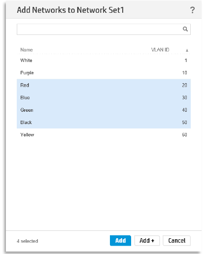
After clicking Add you can select one specific network that will be the Native VLAN, being the default untagged network. This is often used for PXE traffic.
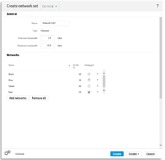
Finally click Create or Create+ if you want to create additional Network Sets.
Now that we have created Network Sets we will create a Logical Interconnect Groups (LIG) that will use these Network Sets.
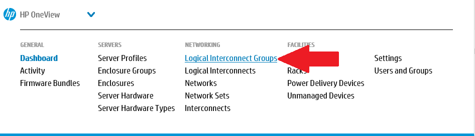
Select the Top Level Menu, under the Networking section select Logical Interconnect Groups
Click the +Create Network Set button at the top left.
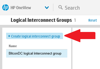
Provide a name for the LIG and click Add Interconnect to select the appropriate Virtual Connect modules in the right slots. Supported modules are VC Flex-10, VC Flex-10/10D and VC FlexFabric.
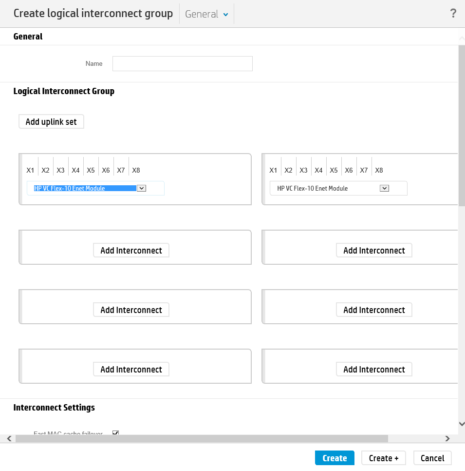
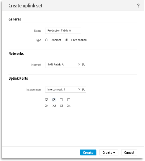
Once the VC modules are selected, Uplink sets will be created. For this click the Add Uplink Set button.
The screen will give the options to select the type of protocol (Ethernet or Fibre Channel) and the connection mode (Automatic or Failover).
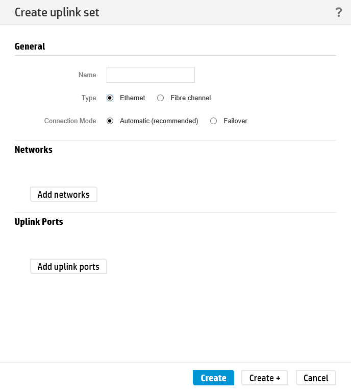
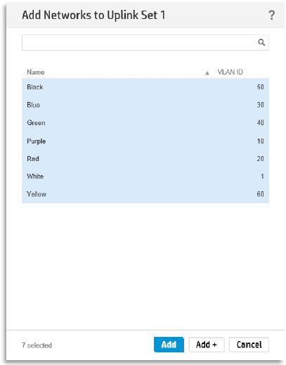
Click the Add Networks button to select the networks to add. By not selecting a Network or multiple Networks, they will be Internal Ethernet Networks within the Logical Interconnect that is applied to each enclosure from the Logical Interconnect Group.
A search field is provided to quickly locate a specific Network or multiple Networks. After searching you can either Left Click to select a single network or SHIFT/CTRL+Left Mouse Click to multi-select networks.
Once all of your networks are selected, click the Add button, or click the Add+ button to continue to add more networks by searching.
Make sure to mark the appropriate network as Native if the VLAN on the upstream switch is also the Native or Default VLAN.
Finally add also Uplink ports for connectivity to the ‘outside world’.
Select at least one port from each Ethernet Module. To quickly add multiple Uplink Ports, first search for a common port (eg. X5), select them, click the Add+ button, then change the search to another port (eg. X6) and click the Add button.
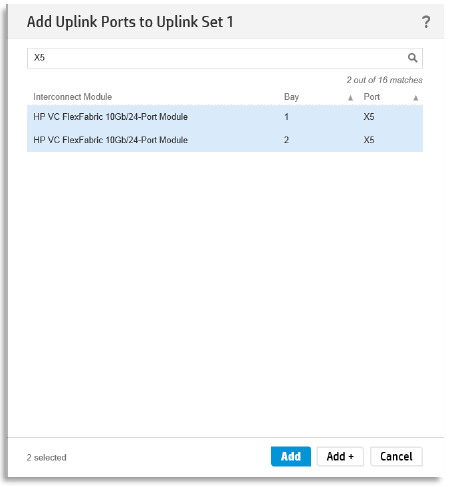
When the internal and uplink ports are selected, click the Create button.
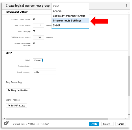
Know also that during the creation you have the possibility to change Interconnect settings like Fast MAC Cache Failover, IGMP Snooping, Loop Protection and SNMP settings. Just scroll down on the configuration page or change the View settings.
Similar actions must be done to create Fibre Channel Uplink sets.
Now we created all the prerequisites for the networking part inside HP Oneview.
The next step will be the discovery of hardware inside Oneview and apply these network configuration and firmware baselines to this hardware. I will explain this in a next blog post.